Narrowband PLC Communication – an Excellent Diagnostic Tool
Within the smart grid, PLC communication over high voltage (230 V) belongs to the dominant transmission channels. The area of the operated territory is often up to 1km2 , and there are plenty of factors with negative influences on PLC signal strength, including topology changes, parasitic impedance from customer behaviour, or significantly high disturbance because customers don’t respect valid EMC standards. Fortunately, the small number of high voltage lines means that there is no problem with own line impedance at lower transmission frequencies.
As for medium voltage (up to 35 kV) lines, the situation for PLC signal transmission up to 500kHz is favourable. The change of topology is missing, so the MV line’s impedance remains the only one dominant load. The area of the MV distribution network has a radius of up to 30 km; these distances are mainly covered by overhead lines. On the other hand, underground cables lines can reach up to 5 km.
Let’s consider the situation within the power network. At the 50Hz frequency, we have to take into account line resistance within the line length of several kilometres. The wave length of a signal with a frequency up to 500kHz (used by PLC systems) is clearly shorter than the used line.
In this case, the signal acts like a wave, and it is thus necessary to take into account total line impedance. We can compare it to the integrated RLC element formed by its parasitic characteristics, when the higher frequencies suffer higher attenuation.
While inductance is similar for both overhead and cable MV lines, there is a significant difference at capacity reached. Cable line capacity (because of very tight cable placement, or single wire shielding) reaches hundreds of nF on 1 km, whereas overhead line capacity is thousands of times lower, which has an influence on total impedance. Therefore, overhead lines have significantly lower attenuation with growing frequency in comparison to cable lines.
BPL vs. PLC on Medium Voltage lines: (non) surprising winner
There are couple of interesting findings if we compare transmission characteristics of broadband and narrowband communications over MV lines. This comparison occurs on cable lines, capacity coupling was used in an inter-phased implementation.
A single phased implementation – with one pole connected to the wire and the second one grounded – was not used because of the high level of disturbance arising from the ground connection). Several lines were compared (the longest of them reached 15 km) in a point-to-point connection.
BPL modems (at the moment let’s put aside their problematic legal anchorage) with the frequency range of 2-30 MHz were able to communicate to the maximum distance of 500 m with the real transmission rate of 100 kbit/s, as a result of the unequal characteristics of the transmission channel in the whole of its bandwidth.
On the other hand, narrowband modems with communication frequency up to 500 kHz that used PRIME and G3-PLC standards, reached comparable rates, even at a distance of 30 times longer in comparison with BPL (the length of line was 15 km only), and, moreover, no repeater was used, which is crucial especially for overhead lines.
There is also another surprising finding: the real transmission rate exceeds competitive GPRS channels. During the testing of single lines (MV cable lines that supplies an electric arc furnace), it was also found that the short packet in the band up to 100 kHz reliably overcomes all disturbances arising from operation of this load, with defined latency.
This fact can be crucial for power distributors: Medium Voltage Power Line Carrier communication can be reliably used for ordering distribution networks. Orders and control commands are not large from the data point of view, but the defined latency is requested.
Added value of Medium Voltage PLC communication: line diagnostics
Another specific characteristic was discovered during the measuring of line diagnostics (accompanied with system reliability increases). It is necessary to realise that a communication PLC modem is a permanently connected receiver that evaluates all catching signals. Beside the fact that it is possible to detect a line interruption (for example if a tree has fallen on an overhead line), we can also identify other types of malfunctions.
The most common malfunctions that lead to line (both overhead and cable) degradation, have two states. At the beginning, there is a high-ohm state that, over time, passes to a low-ohm state i.e. short circuit. A high number of MV line malfunctions are becoming apparent by isolation degradation. Figure 1 shows how the malfunction proceeds and what the result of the malfunction is.
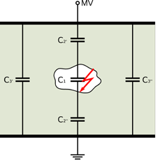
Capacity C1 shows the capacity of the gas cavity inside the isolation. The capacities C2‘ and C2‘‘ show capacity of the rest of healthy isolation, and capacity C3‘ and C3‘‘ is the capacity of the single insulator.
In the cavity, partial discharges are generated, and, gradually, degrade the affected place. The state of this place changes from high-ohm to low-ohm (see Figure 2).
UB is the breakdown voltage of a partial discharge in the cavity. Short ignition of partial discharges causes current impulses. These impulses are superimposed on basic voltage with significantly higher frequency, and this frequency is possible to catch by utilising the receiver of an MV PLC modem.
If we use a relative method, we detect the rise of a disturbance in comparison with the previous state, which is the diagnostic signal. At the cable lines, this is a clear-cut beginning of isolation state malfunction. At the overhead lines, a corona can appear as well, as it has similar physical characteristics.

There is an advantage at medium voltage level: low voltage gradient. It means that circumstances for corona creation are extraordinarily unfavourable (the corona is connected mainly with extra-high voltage lines). On the MV level, especially in dusty environments where the dust together with high humidity precipitates on isolators, conductive routes can be created which is the beginning of isolator degradation.
Conclusion: Long Live Medium Voltage PLC Communication
MV PLC communication can reliably compete with radio transmissions. For example, WMBus is similar a communication rate and volume of transferred data point of view, but it does not have the same radius. SIGFOX, on the other hand, has a similar radius, but is limited by the volume of the transferred data.
GSM has the needed rate and coverage, but it has no defined latency, and it depends on service offerings from a third party. Various radio-relay connections must be licensed within the telecommunication office and they only have point-to-point connections.
In comparison with radio transmissions, transmission over MV lines is not susceptible to intentional disturbance, and it has 100% coverage. MV PLC modem deployment brings new benefits to the area of power supply reliability.
The actual situation enables the indication of potential threats in time, and simplify malfunction searches. Also, the space for significantly sophisticated diagnostics with minimum of additional investments is open, as the most expensive part of the device (i.e. the coupling unit) can be used together with a MV PLC modem.