How to create comprehensive Partial Discharge Diagnostic System
Creating a comprehensive partial discharge diagnostic system is essential for monitoring and assessing the condition of electrical insulation in high-voltage equipment. This article explores how to develop such system, highlighting key concepts, components, and methodologies.
Introduction
The degradation of insulation state in high-voltage systems can be caused by various factors, including partial discharges (PD). Partial discharges are small electrical discharges that do not completely bridge the insulation between conductors. They gradually deteriorate the insulation, eventually leading to a breakdown (complete loss of insulation). The development of a comprehensive partial discharge diagnostic system is crucial for early detection, enabling real-time monitoring and enhancing the lifetime prediction of high-voltage equipment.
How do partial discharges develop?
Partial discharges occur in localized regions within or on the surface of insulation due to small breakdowns of the dielectric material. As the insulation degrades, the frequency and intensity of these discharges increase. They are characterized by short-duration, high-frequency electromagnetic pulses, which can be detected and analyzed to assess the insulation’s health.
In order for a partial discharge to happen, system must meet at least one of the following triggering factors:
- Voltage gradient: A high electric potential difference across the insulation.
- Steepness gradient: Rapid changes in electric field distribution, especially at voltage peaks.
- Velocity gradient: Fast variations in voltage, such as those caused by power converters or switching events.
What are the basic types of partial discharges?
There are three forms of partial discharges:
- Internal discharge: Caused by inhomogeneous insulating materials leading to weak spots inside the insulation.
- External discharge: Due to surface contamination or insufficient insulation clearance, especially in outdoor environments.
- Corona discharge: Occurs in regions of high electric field intensity near conductors, often resulting from conductor geometry or spacing.
What is the partial discharge measurement chain?

Firstly, the measuring sensor detects the electromagnetic pulse, either directly via a capacitive divider or indirectly through current flow using a Rogowski coil. Secondly, the weak partial discharge signal must be amplified with correction amplifier.
Finally, the local processing unit removes ambient noise and processes the PD pulse to identify its occurrence and magnitude. Broadband and narrowband processing methods are employed to filter noise and extract the PD signal accurately.
All of the collected data is archived and presented in an advanced system, such as PD Doctor. This system records critical information, such as the time of the discharge, its magnitude, and the phase of the fundamental harmonic at which it occurred. It also provides automated monitoring and real-time diagnostics which notifies user in case of an event, and uses artificial intelligence to predict the remaining lifetime of equipment based on PD activity trends.
How to recognize partial discharges?
When detecting partial discharges, we use the Electromagnetic Pulse Detection. Partial discharges generate electromagnetic pulses that are similar to Dirac pulses in shape, with a wide frequency spectrum resembling white noise. These pulses can be detected in various frequency bands, and their properties can be analyzed for diagnostic purposes.
There are various possible sensing techniques. For the best frequency response, use active sensing with a capacitive or resistive divider directly connected to the high-voltage equipment or capacitive sensors attached to insulated parts of the cable. Another, less sensitive way is to measure the induced leakage current in the conductor with Rogowski coils or with UHF antennas capturing high-frequency emissions from PD without the need of physical connection to the high-voltage circuit.
How to evaluated measured data?
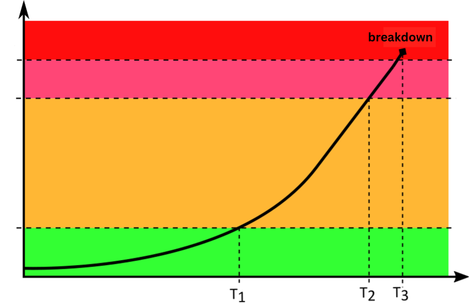
The limits for PD activity, which define operational zones, are based on manufacturer recommendations and field data from operators. Continuous online diagnostics, as opposed to offline diagnostics, allow real-time monitoring and quicker identification of fault conditions, reducing the risk of unexpected failures.
This allows for basic evaluation of reaching certain thresholds requiring further investigation, localizing source of discharge by installing sensors at both ends of a cable and calculating residual lifetime of equipment insulation thanks to predictive algorithms.
For offline diagnostics, portable PD recorders can be deployed at critical points in the system. These devices store PD activity data on an SD card for later analysis. This is useful when continuous online monitoring is not feasible, providing an intermediate step to assess insulation health during scheduled maintenance.
Conclusion
The creation of a comprehensive partial discharge diagnostic system involves multiple stages, from detecting and filtering PD signals to analyzing and archiving them for lifetime prediction. With modern systems, such as PD Doctor, operators can ensure real-time diagnostics, preventing sudden failures and optimizing equipment lifespan. As insulation systems degrade, PD monitoring is an indispensable tool in maintaining the safety and reliability of high-voltage equipment.